Linear Induction Motors
Linear Induction Motors (LIMs)
Overview
Linear induction motors (LIMs) are high-speed, non-contact linear motors capable of velocities up to 1800 in/sec [45 m/s]. Operating on the same principle as rotary squirrel cage induction motors, these motors excel in applications requiring rapid movement of large payloads where precision positioning is not critical.
The system consists of a 3-phase coil assembly and a reaction plate. Motors can connect directly to AC power for single-speed operation or pair with variable frequency drives for precise speed control, reversibility, and dynamic braking.
How Linear Induction Motors Work
Linear induction motors function like rotary induction motors that have been “unrolled” to create linear motion. The system has two components: the primary (coil assembly) and secondary (reaction plate), which interact only when powered.
When three-phase AC power is applied, a traveling electromagnetic flux wave moves across the primary, inducing electric current in the conductive reaction plate. This current interacts with the magnetic flux to produce linear force. Speed varies by adjusting input frequency with a variable frequency drive.
A bearing system maintains the air gap between components. Either the primary or secondary can be fixed while the other moves, providing design flexibility. Force is proportional to the motor’s active surface area.
Key Components
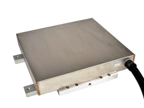
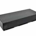
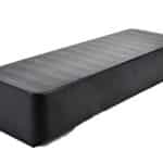
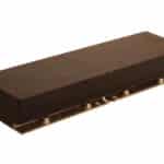
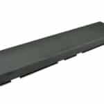
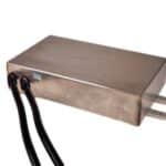
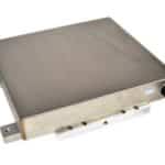
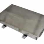
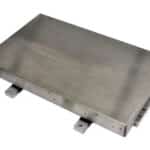
Primary (3-Phase Coil Assembly)
Three-phase coils are wound into a steel lamination stack with thermal protection, then encapsulated in thermally conductive epoxy. Steel mounting angles with pre-drilled holes enable easy installation.
Configurations:
- Single-Sided: One coil assembly with aluminum plate (0.125″ thick) backed by steel plate (0.25″ thick)
- Double-Sided: Two coil assemblies facing each other (0.25″ gap) with aluminum or copper plate (0.125″ thick) between
Multiple assemblies can be combined for higher forces.
Secondary (Reaction Plate)
Customer-supplied reaction plate made from standard 1018 steel, aluminum, and/or copper. The traveling flux wave induces current in this conductive material, which interacts with the magnetic field to create force.
Requirements:
- Single-sided: 0.125″ aluminum or 0.080″ copper plate + 0.25″ steel backing
- Double-sided: 0.125″ aluminum or copper plate only
- Length: Coil length + stroke distance
Performance Specifications
Force Output:
- Individual units: Up to 214 lbs [950 N] peak force
- Standard configurations: Up to 720 lbs [3200 N] at 3% duty cycle
- Multiple motors for higher forces
Speed & Acceleration:
- Maximum velocity: 1800 in/sec [45 m/s]
- Acceleration: 3-4 g’s
- Variable speed control with VFD
Air Gap: 0.040″ – 0.060″ [1 – 1.5 mm]
Duty Cycle Force Multipliers:
- 50% duty: Force × 1.75
- 15% duty: Force × 5
- 3% duty: Force × 8
Air Gap & Thrust Relationship
The clearance between the coil assembly and reaction plate directly affects force output. As gap increases, thrust decreases proportionally due to reduced induced current and weaker magnetic field strength.
Design Standard: Most LIM designs use 0.125″ [3 mm] clearance, accounting for epoxy encapsulation and protective casing. A bearing system maintains consistent gap throughout operation.
Important: Larger clearance requirements may necessitate higher-capacity motors. Consult manufacturer for applications requiring gaps exceeding standard specifications.
Advantages & Limitations
| Advantages | Limitations |
|---|---|
| High Speed – Up to 1800 in/sec with 3-4 g acceleration | No Precision Positioning – Not suitable for accurate positioning applications |
| Non-Contact Operation – Zero friction, no wear parts | Customer-Supplied Components – Requires reaction plate and bearing system |
| Simple Design – Only 2 main components | Air Gap Critical – Requires precise 0.040″-0.060″ gap maintenance |
| No Maintenance – Contactless design eliminates maintenance | Gap-Dependent Force – Thrust decreases as clearance increases |
| Wide Speed Range – Variable control from stall to max velocity | Power-Dependent – Requires continuous power for force generation |
| Scalable Force – Combine multiple assemblies for higher thrust | Individual Force Limit – Single units limited to 214 lbs peak |
| Reversible – Bidirectional motion with dynamic braking | |
| Flexible Mounting – Either coil or plate can be moving element | |
| Easy Installation – Pre-drilled steel mounting angles |
Control Options
Single Speed: Direct AC line connection Variable Speed: Adjustable frequency drive (VFD) for precise control Features: Reversible operation, dynamic braking, stall capability
Design Flexibility
- Either coil assembly or reaction plate can be the moving component
- Rotary motion possible with disc-shaped reaction plate
- Multiple coils can operate together for increased force
- Non-magnetic stainless steel barriers available for harsh environments
Applications
Linear induction motors excel in high-speed material handling and transportation where precision positioning isn’t required:
Industrial:
- Conveyor systems and material handling
- Crane drives
- Baggage handling systems
- High-speed sorting and inspection
Transportation:
- Maglev propulsion systems
- Hyperloop technology
- Personal rapid transit
Theme Parks & Entertainment:
- Roller coaster launch systems (Big Thunder Mountain, California Screamin)
- Water ride propulsion using hydromagnetic technology (Dawwama, Thunder Rapids)
- People mover systems (Tomorrowland Transit Authority)
Why Choose Linear Induction Motors
LIMs are ideal for rapid movement of large payloads, offering speeds exceeding 1800 in/sec and accelerations of 3-4 g’s. The non-contact design eliminates wear components and maintenance requirements while providing wide speed range flexibility. Simple two-component architecture reduces complexity, and pre-mounted steel angles ensure straightforward installation with standard AC power or VFD integration.
Ordering Information
Individual linear induction motors available up to 214 lbs [950 N] peak force. Multiple coil assemblies can be configured for higher force requirements. Standard sizes available in various widths and lengths.
Products
| Product Number | Duty Cycle | Force @ Duty Cycle | Power @ Duty Cycle | Current @ Duty Cycle | Input Voltage | Length | Width | Weight | |
|---|---|---|---|---|---|---|---|---|---|
|
LMA-06-062 | 100 % | 14 lbs / 62.5 N | 0.70 kW | 3.0 amps | 380 VAC / 3 Θ | 16.3 in / 413 mm | 7.0 in / 178 mm | 42.2 lbs / 19.1 kg |
|
LMAA-04-01 | 15 % | 10.5 lbs / 47 N | 0.37 kW | 5 amps | 208 VAC / 3 Θ | 8.7 in / 223 mm | 3 in / 75 mm | 6.6 lbs / 3 kg |

|
LMAC3208C23B99 | 100 % | 35 lbs / 155 N | 1.6 kW | 13 amps | 230 VAC / 3 Θ | 31.75 in / 806.5 mm | 8.0 in / 203.2 mm | 121 lbs / 54.9 kg |

|
LMAC3208C23D15 | 15 % | 180 lbs / 800 N | 7.8 kW | 27 amps | 480 VAC / 3 Θ | 32.0 in / 813 mm | 8.0 in / 203 mm | 107 lbs / 48.5 kg |
|
LMB-08-140-EC | 5 % | 130 lbs / 578 N | 6.3 kW | 48 amps | 230 VAC / 3 Θ | 19.6 in / 497 mm | 5.3 in / 134.6 mm | 56.3 lbs / 25.5 kg |
|
LMB-16-060 | 65 % | 60 lbs / 267 N | 3.3 kW | 13 amps | 460 VAC / 3 Θ | 38.75 in / 984.25 mm | 9.0 in / 228.6 mm | 140 lbs / 63.5 kg |
|
LMD-03-225-SSE | 3 % | 225 lbs / 1000 N | 29 kW | 100 amps | 400 VAC / 3 Θ | 18.4 in / 467 mm | 10.9 in / 276 mm | 107 lbs / 48.5 kg |
|
LMG-03-325-SSE | 3 % | 325 lbs / 1445 N | 36 kW | 185 amps | 400 VAC / 3 Θ | 19.5 in / 495 mm | 18.4 in / 466 mm | 200 lbs / 91 kg |
|
LMG-06-650-SSE | 3 % | 650 lbs / 2891 N | 72 kW | 370 amps | 400 VAC / 3 Θ | 31.9 in / 809 mm | 19.5 in / 495 mm | 420 lbs / 190 kg |
|
LMH-06-900-SSE | 3 % | 719 lbs / 3200 N | 110 kW | 450 amps | 400 VAC / 3 Θ | 31.9 in / 810 mm | 21.5 in / 546 mm | 560 lbs / 254 kg |