Linear Stepper Motors
Linear Stepper Motors
Overview
H2W Technologies’ linear stepper motors provide precise open-loop positioning for light payload applications. These motors achieve speeds up to 80 in/sec [2 m/sec] with strokes extending to 144″ [3.6 m]. When paired with microstepping drives and indexers, they deliver exceptional position, velocity, and acceleration control.
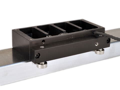
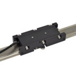
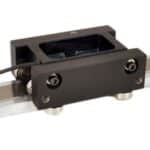
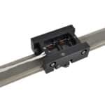
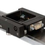
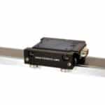
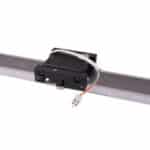
The system consists of a compact moving forcer guided by roller or air bearings along a precision-ground platen. Bearings support your payload while maintaining the critical 0.001″ [0.025 mm] gap between platen and forcer.
Motion control is achieved through step and direction signals sent to the 2 or 4-phase forcer via power cable. Full-step resolution is 0.010″ [250 microns]; microstepping delivers 0.00004″ [1 micron] precision.
Each linear stepper motor integrates motor, bearings, and positioning system into one complete stage. Adding a linear encoder enables closed-loop operation.
Key Advantages
- Compact, low-profile design with minimal cross-section
- High-speed capability
- Cost-effective positioning stage solution
- No servo tuning required
- Multiple forcers operate on single platen
Common Applications
- Pick-and-place systems
- Wire bonding equipment
- Parts transfer automation
- Fiber optic positioning
Pros vs Cons
Pros:
- No servo tuning required—simplifies setup and commissioning
- Cost-effective solution for precision positioning applications
- Compact footprint with low-profile design
- Multiple forcers can operate independently on a single platen
- High-speed capability up to 80 in/sec [2 m/sec]
- Micron-level positioning accuracy with microstepping
- Open-loop operation reduces system complexity
- Integrated motor, bearings, and positioning in one package
Cons:
- Limited to light payload applications
- Requires clean, dry operating environment
- No inherent position feedback (unless encoder added for closed-loop)
- Roller bearing models can slide when unpowered in vertical orientation
- Debris accumulation on platen affects performance
- Requires precise air gap maintenance (0.0015-0.002″)
- Performance depends on proper driver and power supply selection
How Linear Steppers Work
Linear stepper motors operate on electromagnetic principles, converting electrical pulses directly into precise linear motion without rotary-to-linear conversion mechanisms.
Basic Operation
The motor consists of a moving forcer with toothed laminations and a stationary platen with matching teeth. When electrical current flows through the forcer windings, it creates a magnetic field that interacts with the permanent magnets and toothed surfaces. This electromagnetic interaction generates force that moves the forcer along the platen.
Step-by-Step Motion
Each electrical pulse sent to the motor causes the forcer to move one discrete step. The distance per step depends on the tooth pitch and motor design:
- Full Stepping: Each pulse moves the forcer 0.010″ [250 microns]
- Microstepping: Dividing each full step creates finer resolution—256 microsteps per full step yields 0.00004″ [1 micron] movement per pulse
Phase Control
Linear steppers use 2 or 4-phase windings. The driver energizes these phases in precise sequences, creating a traveling magnetic field that pulls the forcer along the platen. The step and direction signals from the controller determine movement distance and direction.
Positioning Accuracy
Open-loop operation means the system assumes each commanded step occurs accurately. For applications requiring position verification, adding a linear encoder creates a closed-loop system where actual position is measured and corrected.
The air gap between forcer and platen (0.001″ [0.025 mm]) is critical—too large reduces force, too small risks contact and binding.
Construction
Linear stepper motors consist of two primary components:
Moving Forcer Assembly
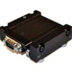
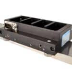
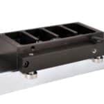
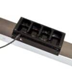
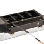
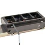
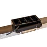
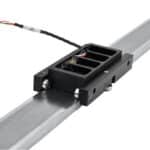
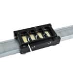
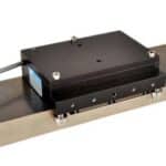
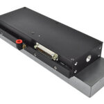
The forcer features an aluminum housing containing motor windings, lamination stacks, and permanent magnets. Active lamination surfaces are slotted to form 0.040″ [1 mm] pitch teeth. Coil terminations connect via D-connector or flying leads. Top-mounted holes accommodate payload attachment. Forcers vary in width and length based on force requirements. Multiple independent forcers can operate on a single platen.
Stationary Platen
The platen is a precision-ground steel bar or tube with 0.020″ [0.50 mm] wide surface teeth. Hard chrome plating and epoxy filling create a flat air-bearing surface. Available widths range from 1.25″ to 3.0″ [31.8 mm to 76.2 mm]. Platen length corresponds to stroke requirements. Single-piece platens extend to 144″ [3.6 m]; longer strokes use sectional platens.
Technical Specifications
Electronics Requirements
Linear stepper motors require a full-step or microstepping driver with appropriately rated power supply. Full stepping produces 0.010″ [0.25 mm] movement per step. Microstepping divides full steps by the microstep count—256 microsteps per full step yields 0.00004″ [1 micron] resolution.
Environmental Considerations
These precision devices require clean, dry mounting environments. Prevent debris accumulation on the platen surface.
Mounting Guidelines
Mount platens to flat (better than 0.003″/ft [246 microns/m]), rigid surfaces using bottom-mounted threaded holes. Attach payloads to top-surface threaded holes on the forcer. Motors mount in any orientation. Vertical mounting requires additional force to overcome gravity; roller bearing forcers slide downward when unpowered, while depressurizing air bearing forcers locks them in position.
Air Gap Setting (Roller Bearing Models)
Set forcer air gap to 0.0015-0.002″ [38-50 microns]. Proper gap setting allows smooth manual movement along the entire platen length. Reset the gap if the forcer becomes difficult to move or contacts the platen. Download detailed air gap setting instructions.
Operation
Linear stepper motors operate through connection to a motion controller/indexer and stepper motor driver with power supply.
Control Flow
- Program Development: Write motion profiles on PC/laptop and download to motion controller/indexer. Parameters include speed, acceleration, deceleration, and move distance.
- Command Generation: Controller/indexer commands required step count and direction based on program parameters.
- Signal Processing: Microstepping driver converts step and direction inputs into motor movement using set current. Driver bus voltage determines maximum motor speed.
- Motion Execution: Motor moves specified distance at programmed speed and acceleration.
Part Number System
[Include part numbering chart/diagram here]
Products
| Product Number | Force | Bearing Type | # of Phases | Current | |
|---|---|---|---|---|---|
|
LMSS0602-2WW0 | 2.0 lbs / 8.9 N | Roller | 2 | 1.5 amps |
|
LMSS0604-2WW0 | 4.0 lbs / 18 N | Roller | 2 | 3.0 amps |
|
STS-0213-R | 2.3 mm / 10 in | Roller | 2 | 2.0 amps |
|
STS-0213-RV | 2.3 lbs / 10 g | Roller | 2 | 2.0 amps |
|
STS-0620-R | 6.0 lbs / 27 N | Roller | 2 | 2.0 amps |
|
STS-0620-RN | 6.0 lbs / 27 N | Roller | 2 | 2.0 amps |
|
STS-0620-RNB | 6.0 lbs / 27 N | Roller | 2 | 2.0 amps |
|
STS-0620-RNL | 6.0 lbs / 27 N | Roller | 2 | 2.0 amps |

|
STS-0620-RNR | 6.0 lbs / 27 N | Roller | 2 | 2.0 amps |
|
STS-1220-A4U | 11 lbs / 49 N | Air | 4 | 2.0 amps |
|
STS-1220-AP1 | 11 lbs / 49 N | Air | 2 | 4.0 amps |
|
STS-1220-AP2 | 11 lbs / 49 N | Air | 2 | 4.0 amps |
|
STS-1220-AP3 | 11 lbs / 49 N | Air | 2 | 4.0 amps |
|
STS-1220-AP4T | 12 lbs / 53 N | Air | 2 | 3.8 amps |
|
STS-1220-APM | 12 lbs / 53 N | Air | 2 | 3.8 amps |
|
STS-1220-R | 11 lbs / 49 N | Roller | 2 | 4.0 amps |
|
STS-1220-RV | 7.2 lbs / 32 N | Roller | 2 | 3.0 amps |
|
STS-2030-A | 20 lbs / 89 N | Air | 2 | 4.0 amps |
|
STS-5030-A4 | 50 lbs / 222 N | Air | 4 | 4.0 amps |